MARBLES DIY Section - Maytrix

good place to post your setup and get feedback from others.

Maytrix Update

Postby Marbles_00 on Tue Dec 09, 2008 5:25 am

I finally got around to finish off the wiring...though it's not permanently installed, it allowed me to try out the circuitry, and I/O. I connected to the inputs:
    Input 1: AM/FM Tuner
    Input 2: External CD Player
    Input 3: Line-out from motherboard
So far I have controlled the Maytrix to playback from each input on the mainfloor outputs...it was too late to try out the upstairs outputs, but it should work the same. I ran each output to the familyroom zone, and controlled everything via VNC to the music-server running a modified ZoneSkin4. It ran pretty good.

Some known issues that I have to work on though:
1) I'm running now two devices off parallel ports. My VFD and the Maytrix. The LPT1 port off the motherboard is working fine, but I had installed a PCI Parallel port card, and though initially it worked fine, it would fault when the system came out of S3 standby. It would remain un-operable until either I rebooted, or went into Device Manager and changed some of its settings. So what I'm looking at now is a USB2LPT device. Right now the MB LPT1 port is running the Maytrix and I have disconnected the VFD from the system as the PCI parallel port card is not reliable enough.

2) For some reason a freezer compressor would make the Maytrix switch outputs before swapping the ports from the PCI card. I also dropped some Lua commands in Girder, which I figured may have been increasing the chances of this interference to occur. Since doing these changes the Maytrix has been more reliable.

3) Some of the connector headers on the Maytrix have to be replaced with ones that lock the connector in place as currently they have a tendency to pop off.

Once I get it cleaned up some, I will take pictures and update my site.
Marbles_00
 
Posts: 1867
Joined: Wed Apr 06, 2005 12:44 pm
Location: Canada

Re: MARBLES DIY Section - Maytrix

Postby Marbles_00 on Thu Dec 11, 2008 12:13 pm

Pics added to both the Whole House Audio Distribution, and the sub-site Phase 2 - The Maytrix.
Marbles_00
 
Posts: 1867
Joined: Wed Apr 06, 2005 12:44 pm
Location: Canada

BSG Amplifier +/-15VDC Output Connector

Postby Marbles_00 on Fri Dec 12, 2008 6:24 am

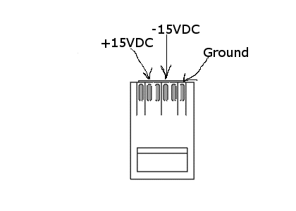
Anyone with one of those BSG amps have themselves a pretty good regulated +/- power supply at their disposal. The only issue is that it's limited in it current draw to 200mA. The actual outputs are +15VDC and -15VDC. The actual use for this was for that little processing unit that was included with the purchase of the amp (though for most of us...we ditched that). I read around different forums about these amps that alot of people had issues with RJ-11 4 conductor (or RJ-14) extensions. Some people got these with the amps...well they won't work. The phone cord required is a RJ-11 6 conductor (or what it really is called...RJ-25). This being because the ground is on the one external pin (pin 6 if you follow the conventional methods of wiring). Below is a diagram of the BSG aux power out connector.

Have fun using this power source in upcoming projects.

*EDIT*
I should also note that all the pre-made RJ-25 patch cabling I have, the color wire to pinout is crossed from end to end. Example there are the following colors: Blue, Yellow, Green, Red, Black, White. At one end (following the actual pinout of a standard RJ-25 connector:
    Pin 1: Blue
    Pin 2: Yellow
    Pin 3: Green
    Pin 4: Red
    Pin 5: Black
    Pin 6: White
The other end is:
    Pin 1: White
    Pin 2: Black
    Pin 3: Red
    Pin 4: Green
    Pin 5: Yellow
    Pin 6: Blue

So in actuality, if looking at the BSG amp RJ-25 jack, and following the pinout standard:
    Pin 1: Gnd
    Pin 2: NC
    Pin 3: -15VDC
    Pin 4: NC
    Pin 5: +15VDC
    Pin 6: NC
Attachments
BSG_Pow_out.png
BSG_Pow_out.png (6.67 KiB) Viewed 19382 times
Last edited by Marbles_00 on Wed Sep 23, 2009 10:47 am, edited 1 time in total.
Marbles_00
 
Posts: 1867
Joined: Wed Apr 06, 2005 12:44 pm
Location: Canada

Thermal Fan Ctrl

Postby Marbles_00 on Sun Jul 19, 2009 1:47 pm

I found a DIY thermal controlled fan circuit here: http://www.heatsink-guide.com/tempcontrol.htm . I know, there are plenty of them on the web, but something about this circuit really caught my attention.

It is a really simple circuit. Though I haven't built one for any of my systems...YET, I did build one for a friend's system and it worked really good. I ended up using an IRFZ34NS, which is a surface mount D-PAC, in place of the IRFZ24N, a standard 10k pot as opposed to the trimmer pot, and a YSI 44006 10k Precision thermistor...as I had all those parts readily available.

Just remember to pay attention to this warning:
Fan RPM monitoring will NOT work with this temperature control. Don't try to connect the rpm signal wire to your motherboard. It will not work and might damage your motherboard. Building a temperature control that works with rpm monitoring would require the usage of a P-Channel MOSFET (and a different circuitry), which are not as widely available as N-Channel Power MOSFETs.


Have fun
Last edited by Marbles_00 on Tue Sep 22, 2009 2:42 pm, edited 1 time in total.
Marbles_00
 
Posts: 1867
Joined: Wed Apr 06, 2005 12:44 pm
Location: Canada

Single Bay Gray-Hoverman

Postby Marbles_00 on Tue Sep 22, 2009 2:39 pm

Well, I started a new project. The goal is to bring multiple television programming to the HTPC. I was testing a FTA satellite setup, but that's been down for the last little while :wink: :lol: , so I've been looking at other ways of getting some digital TV, even some high def content...well, some of you most likely know...or even have played with OTA (over-the-air) by just using a simple antenna to get VHF/UHF signals, well here's a link to my build of one of the best DIY antennas that can be constructed called the Gray-Hoverman:
https://sites.google.com/site/maycreate ... up/my-sbgh

It is actually pretty easy to build. Took me about 3 hours, spanned across a few nights.

There is a wealth of information on OTA and the Gray-Hoverman here:
http://www.digitalhome.ca/forum/forumdisplay.php?f=81

Before taking on this project...or even wanting to explore OTA in general, find out what you can get around your dwelling by using this website: http://www.tvfool.com

Also this site: http://www.antennamap.com
will draw a direct line to the transmitters to aid in antenna alignment.

I wasn't sure about all this at first, but when I pulled in CBC in HD with a crystal clear 1080i image...then a couple of others in HD as well, all with this DIY antenna mounted in a crappy location for testing purposes (leaned up against an inside wall, sitting on the floor of my parents house)....well, I was sold. I'm now fixing up the antenna with the hopes to pull in some HD from you guys in the states (CBS, NBC, Fox, and ABC), from either Buffalo or Erie.

Oh and this is a main reason while I've held back in releasing my Glass skin...as I wanted to get some sort of TV playback scheme to include with the skin.
Last edited by Marbles_00 on Thu May 12, 2011 5:17 pm, edited 1 time in total.
Marbles_00
 
Posts: 1867
Joined: Wed Apr 06, 2005 12:44 pm
Location: Canada

Mclapp-4

Postby Marbles_00 on Wed Oct 14, 2009 1:25 pm

I decided to try out a second type of antenna called the Mclapp-4. It is a bowtie antenna, which has been designed, modeled and simulated using 4Nec software by the individual who goes by the nic "mclapp" over at the digitalhome.ca website. The main discussion page can be found here:
http://www.digitalhome.ca/forum/showthread.php?t=100137

Like mentioned above, find out first what's in your area by going to TVfool.com (linked above).

My build can be found here:
https://sites.google.com/site/maycreate ... p/mclapp-4

It is a reflectorless model right now, but in testing I was able to get ABC, which is the first time ever. Does this make it a better antenna over the Hoverman? Not sure, as the test conditions were a little different. Last night I pulled the livingroom blinds up, which I never did when testing the Hoverman. Also, I was able to prop this antenna up higher, so it was more exposed, which I never did with the Hoverman.

So my intentions are to use this antenna for getting all the Canadian channels, and expand the Hoverman build to a dual-bay, and change its reflectors to 1/4" copper rods/tubing - spaced as indicated in the designs. Then use that antenna to get the American feeds.
Last edited by Marbles_00 on Thu May 12, 2011 5:18 pm, edited 1 time in total.
Marbles_00
 
Posts: 1867
Joined: Wed Apr 06, 2005 12:44 pm
Location: Canada

Re: MARBLES DIY Section - Maytrix

Postby P3rv3rt B3ar on Mon Nov 09, 2009 11:49 am

So Marbles, considering uve built maytrix and all, i thought im gonna ask experts opinion: How hard would it be to mod out-of-box switch to support computer control?

Reason im asking dealer near me is unloading joytech 540c command centers cheaper-than-dirt price. I mean surely i can control unit trough usual girder/IR routine, but id be interested to hack some COM/LPT based control into the unit.
P3rv3rt B3ar
 
Posts: 1364
Joined: Fri Apr 07, 2006 9:52 pm
Location: West Coast Funland

Re: MARBLES DIY Section - Maytrix

Postby Marbles_00 on Mon Nov 09, 2009 11:43 pm

I'm going to say that...anything is possible. For that particular device, I can't say how difficult it would be, as I don't know the inside electronics of how they are doing their switching. You could spend hours at reverse engineering it, and could work for you, or it could be a total bust. Would I take something like that on? Most likely not, since it already has a viable IR control, I'd just get a USB Uirt with an additional IR transmitter, which I would tape across the IR receiver of the box, then just use the xlobby commands to control it that way.

If you do decide to open it up, good luck. Let me know some of the IC's and I could find some datasheets on them. Most of all, half fun doing it.
Marbles_00
 
Posts: 1867
Joined: Wed Apr 06, 2005 12:44 pm
Location: Canada

Re: MARBLES DIY Section - Maytrix

Postby P3rv3rt B3ar on Tue Nov 10, 2009 1:13 am

Yeah i already disected one of them earlier today, and whatta project it was, these guys didnt save on screws. Anyhows there are ICs like ATMEL 544, UTC TF0A, UT8660, 74HC04D, 74HC595D, HEF4051BT, TE330 in it, plus one PIC16 and one (irrelevant) IC which is responsible for Ethernet swithc. I was really hoping i could just patch into buttons and close their circuits as commanded by some basic comp control PCB draw out of DIY-cookbook. But unfortunately buttons (on device) chance source only relative to current source and whats worse sources cycle, so i cant use the common trick to travel into either end first (allthough this wouldnt prolly be pretty for the viewer).

Anyhows encouraged by the fact that i managed to put thing back together (with only couple leftover useless parts) i decided to take a stab at my newly YLODed PS3... Not much longer and the console was back among living, so its pretty safe to say the switch project is gonna be iced for a looong while :D
P3rv3rt B3ar
 
Posts: 1364
Joined: Fri Apr 07, 2006 9:52 pm
Location: West Coast Funland

Re: MARBLES DIY Section - Maytrix

Postby Marbles_00 on Tue Nov 10, 2009 8:25 pm

The Atmel 544 - is some sort of micro-controller/FPGA/CPLD and is most likely the main control in the system. Can't seem to find a datasheet on it yet.

UTC TF0A - not sure what that IC is (TBD), as I can't find a datasheet on it.

UT8660 - can't find a datasheet on this IC (TBD).

74HC04D - hex inverter/buffer
http://datasheet.octopart.com/74HC04D-P ... t-5375.pdf

74HC595D - 8-bit serial-in/serial or parallel out driver
http://www.nxp.com/acrobat_download/dat ... T595_4.pdf

HEF4051BT - 8-ch analog mux/demux
http://www.nxp.com/acrobat_download/dat ... 051B_4.pdf

TE330 - not sure (TBD), can't find any information on this IC.

PIC16 - micro-controller, very popular

If I was going to start anywhere, I'd trace the HEF4051 IC, and determine where it's inputs and outputs goto. I would start there because it is an ANALOG bi-directional switch.
Marbles_00
 
Posts: 1867
Joined: Wed Apr 06, 2005 12:44 pm
Location: Canada

Fractal Antenna

Postby Marbles_00 on Mon Dec 21, 2009 12:36 am

My brother lives in an apartment, and he's indicated to me that his landlord would not go for one of my antennas hanging in the window or out on a balcony. So I started to look into some different antenna design and found out about the Fractal antenna. These are the type of antennas that can be found in cell phones for their compact size. The only drawback to this compact size is the overall gain is less than when using a full sized antenna. So I found the plans for a UHF fractal and decided to give it a try. Here is the link to my google site on the antenna:

https://sites.google.com/site/maycreate ... al-antenna

Needless to say, I was very impressed with it. I was able to pickup numerous stations that are close by. At my parents I actually picked up CBC and OMNI2 from Toronto...30kms LOS away...with the antenna sitting indoors on top of their TV. My brother is only 5kms LOS from the broadcasting stations in Toronto...and with this compact size, he should have no issues what-so-ever in getting some free HDTV, and not bothering anyone in the meantime.

Merry Christmas to him. :D
Last edited by Marbles_00 on Thu May 12, 2011 5:19 pm, edited 1 time in total.
Marbles_00
 
Posts: 1867
Joined: Wed Apr 06, 2005 12:44 pm
Location: Canada

Re: MARBLES DIY Section - Maytrix

Postby samsonlov on Wed Dec 23, 2009 12:17 am

Hey Marbles,

In the U.S. it's illegal for landlords to "restrict" a tenant's "right" to receive broadcasts as long as the antenna is under 2 meters in diameter.

The Commission has adopted an Order (FCC 98-273) further implementing Section 207 of the Telecommunications Act of 1996 to promote consumer choice and competition in the video programming distribution market. The revised over-the-air reception devices rule extends the prohibition on restrictions that hamper consumer use of television antennas, small satellite dishes, and wireless cable antennas to include viewers who rent property and wish to install and use antennas in areas where they have exclusive use, such as balconies or patios. This order also preserves property rights and avoids practical problems by excluding common areas, such as the roof of a multi-dwelling unit building, from the rule.


http://www.fcc.gov/Bureaus/Cable/News_Releases/1998/nrcb8023.html

:)
samsonlov
 
Posts: 220
Joined: Thu Sep 25, 2008 1:39 am
Location: Los Angeles, CA

Re: MARBLES DIY Section - Maytrix

Postby Marbles_00 on Wed Dec 23, 2009 3:27 pm

That's good info to know. I don't know what the rules are up here in Canada. Suppose there is some fine print somewhere in the "tenant" act, or maybe something on the CRTC website. Though left to the CRTC, I can't see it bold well for the end user.
Marbles_00
 
Posts: 1867
Joined: Wed Apr 06, 2005 12:44 pm
Location: Canada

OTA Gray-Hoverman DIY Completed

Postby Marbles_00 on Sun Feb 07, 2010 7:08 pm

Finished off my OTA project. It consists of two Single Bay Gray-Hoverman antennas in the attic. Attached is a Channel Master CM-7777 pre-amp, through about 90' of cable to my HVR-1250 ATSC tuner card in my HTPC. This all equates to over 20 channels of digital programming (almost all of them in HD), and about 10 channels of analog stations (Canada hasn't gone the full switch over to digital until 2011).

What a great DIY project that was.

See the Gray-Hoverman post above for a link to the google site where I documented the project.

Eventually as I add more TV's (or tuners), I will most likely add a CM-3414 distribution amp to the setup.

Now I can get back onto my Xlobby projects.
Marbles_00
 
Posts: 1867
Joined: Wed Apr 06, 2005 12:44 pm
Location: Canada

The Stealth Hawk Antenna

Postby Marbles_00 on Tue May 25, 2010 5:12 pm

So I thought I was done with the OTA project....well...

Come 2011, there will be a couple of stations in my area that will re-position their current digital broadcasting back to their current analog RF antennas, which broadcasts in the VHF range. So I built a Stealth Hawk in the attempts to prepare for this eventual transition, and to pickup some possible future channels in the VHF range.

Pics of my build can be found here:
https://sites.google.com/site/maycreates/ota-setup/my-stealth-hawk

The main discussion of the Stealth Hawk can be found here:
http://www.digitalhome.ca/forum/showthread.php?t=123803

So far, this antenna has performed pretty good, and suits my UHF antenna setup very well. Looking forward to see how this will perform come August 2011 (Canadian digital transition date)
Marbles_00
 
Posts: 1867
Joined: Wed Apr 06, 2005 12:44 pm
Location: Canada

PreviousNext